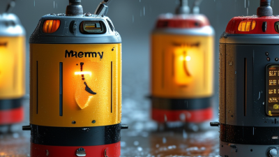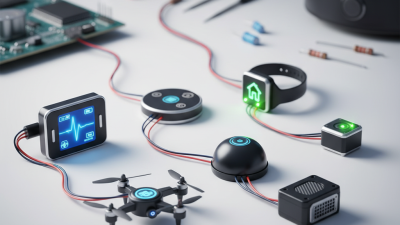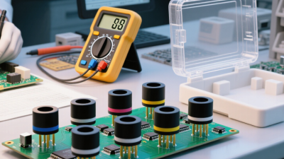
Choosing a buzzer circuit for 2026 means matching the sounder to its supply, control signal, and real operating conditions. A clear Electric Buzzer Circuit Diagram helps buyers see how the supply, switch, driver, and buzzer connect before assembly. Small details matter. A reversed piezo connection or an undersized transistor can turn a simple alert into a silent bench test.
The market context is broader than buzzers alone. World Semiconductor Trade Statistics’ Fall 2024 forecast projected global semiconductor sales of about $626 billion in 2024 and $697 billion in 2025. That figure does not measure buzzer sales, but it shows the scale of the component ecosystem buyers rely on. Analog design engineer Bob Pease once quipped, “My favorite programming language is solder.” His line is a reminder that practical hardware still needs careful testing—not just a neat schematic.
This guide compares common circuit approaches, including direct-drive piezo designs and transistor-switched magnetic buzzers. It will help you check rated voltage, current draw, sound output, polarity, and driver requirements against product datasheets. A diagram can simplify selection, but it cannot replace those checks. One limitation deserves attention: published data on the buzzer-circuit segment itself is scarce, so broad electronics figures should not be mistaken for product-specific evidence. Expect useful guidance, not a perfect shortcut.
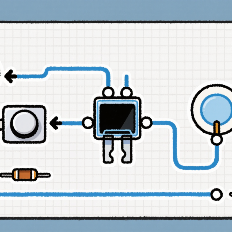
Active and passive buzzers differ by how they produce oscillation. An active buzzer contains an oscillator, so applying its rated DC voltage produces a tone. A passive buzzer needs an external pulsed signal, often from a timer or microcontroller. In a circuit diagram, the active type usually needs a switching transistor and supply connection; the passive type also needs a signal source.
Simple difference. Check the datasheet before choosing: active units may sound continuously on steady power, while passive units let the circuit control pitch and rhythm. A rough rule, not a guarantee.
Compare operating voltage, current, sound-pressure level, and resonant frequency—not just the wiring. Component characterization reports commonly list sound pressure in dB at a stated distance, since readings change with test setup. IEC 60268-5 provides recognized methods for measuring loudspeaker performance; use comparable acoustic test conditions when reviewing buzzer data.
Many small parts specify output near 2–4 kHz, but that range is only a practical screening guide. A quiet bench can mislead: the enclosure and mounting surface may change the perceived volume. I would verify the actual assembly, not trust the schematic alone.
One detail is easy to miss: a passive buzzer’s drive frequency affects both tone and loudness.

A reliable buzzer circuit starts with the load’s rated voltage and current, not guesswork. Read the buzzer datasheet, then compare its rating with your supply.
For a simple example, a 3 V buzzer drawing 20 mA on a 5 V supply needs a series resistor: R = (5 − 3) / 0.02 = 100 ohms. This uses V = IR.
Check that the buzzer is suitable for this method; some active buzzers need a driver, and their current is not a fixed resistance. Small detail. It matters.
Resistor heating also deserves a calculation. Using P = VI, the example resistor dissipates 2 V × 0.02 A, or 0.04 W. A suitably rated resistor provides margin, but confirm its temperature and enclosure conditions.
IEC 60063:2015 defines preferred-number series for resistors; its E24 series contains 24 nominal values per decade, helping designers select practical values such as 100 ohms. Treat that as a selection guide, not proof that a circuit is safe.
Supply tolerance, startup current, and wiring losses can change the result. I still recheck the buzzer’s actual current before choosing parts; the neat calculation can miss real-world variation.
Best Electric Buzzer Circuit Diagram for 2026 Buyers
Select a driver transistor whose collector-current rating exceeds the buzzer’s measured operating current. Do not size it from the circuit’s nominal voltage alone. A magnetic buzzer may draw a brief startup surge, while a piezo buzzer often behaves differently. Check the buzzer datasheet, then measure current during startup and steady operation if possible. For example, if a buzzer draws 80 mA steadily and peaks at 120 mA, a transistor rated for at least 240 mA offers a practical two-times peak-current margin. That margin is not magic. Confirm the rating under the actual temperature and switching conditions.
The rating printed on a transistor datasheet depends on specified test conditions. IEC 60747-7 covers bipolar transistor device ratings, while JEDEC JESD51-1 describes electrical measurement methods used for thermal characterization. Use these references to interpret ratings, not as substitutes for checking your circuit. Also verify that the transistor can dissipate heat safely and that its base receives enough drive current to switch fully. A small resistor, long wires, or a weak control pin can leave the transistor partly on. That wastes power and may cause heating. I have found this easy to miss on a tidy-looking schematic. Test the assembled circuit with the buzzer connected, and check the transistor after repeated operation.
Select a driver transistor rated above the buzzer’s operating current.
The chart uses illustrative buzzer currents and a 2× current-rating target for the transistor. These are design examples, not specifications for a particular buzzer. Check the buzzer’s datasheet and verify the transistor’s thermal limits and circuit conditions before selecting components.
A buzzer’s loudness is not just a comfort detail; it affects safe exposure. NIOSH’s 1998 Criteria for a Recommended Standard: Occupational Noise Exposure sets an 85 dBA recommended exposure limit for an eight-hour workday. Its 3 dB exchange rate means each 3 dB increase halves the recommended exposure time. That makes a buzzer measured at 91 dBA a very different choice from one near 85 dBA, especially during repeated testing. Brief tests matter, too.
Check the sound-pressure level with a calibrated meter, using A-weighting and recording the distance from the buzzer. Test the assembled circuit, not just a component on a datasheet. Enclosures, mounting surfaces, and room reflections can change the reading. A small workshop bench may amplify a sharp tone in ways a quiet test room does not. A single reading can mislead. Measure from the listener’s likely position, and note how long the buzzer sounds during normal use. Compare the measured level and duration with NIOSH’s exposure guidance; do not treat 85 dBA as a universal “safe buzzer” rating. It is an eight-hour exposure recommendation, not a circuit specification. I would retest after changing the housing, because that detail is easy to underestimate.
For a 2026 electric buzzer circuit, enclosure protection deserves attention alongside the wiring diagram. IEC 60529 defines the IP code: the first digit rates protection against solid objects, and the second rates protection against water. For example, IP54 means dust-protected and resistant to splashing water; IP65 means dust-tight and tested against water jets. These are defined test categories, not promises of protection in every installation.
Match the rating to the buzzer’s location. A unit near a washdown area may need a different enclosure from one mounted in a dry indoor control panel. Check the cable entries, seams, and buzzer opening, not just the enclosure label. A single poorly sealed cable gland can undermine the protection of the assembled circuit. Small detail.
IEC 60529 ratings do not describe impact resistance or corrosion performance. Nor does a rating automatically remain valid after drilling or changing the enclosure. Test the completed assembly with its actual cables and fittings. It is easy to overtrust a neat-looking gasket; I would inspect it again after installation, especially where vibration can loosen fasteners. The rating helps compare protection levels, but placement and maintenance still matter.
| Circuit or Buzzer Type | How It Works | Typical Circuit Design Considerations | Example Application | Relevant Enclosure Rating | What the IP Rating Indicates |
|---|---|---|---|---|---|
| Active piezo buzzer | An internal oscillator generates the tone when the buzzer is supplied with its specified DC voltage. | Use a supply within the device’s rated voltage range. A transistor driver may be needed when the control output cannot provide the buzzer’s required current. | Indoor alarms, timers, and status indicators | IP20 or higher, depending on exposure | IP20 provides protection against access by a finger and solid objects of 12.5 mm or larger; it provides no water protection. |
| Passive piezo sounder | Requires an external oscillating or pulsed signal to make sound; tone and pitch depend on the drive signal and sounder characteristics. | Check the sounder’s permitted drive frequency, voltage, and waveform. A microcontroller output may require a driver stage if its electrical limits would otherwise be exceeded. | Electronic alerts with selectable tones | IP20 or IP44, according to the installation environment | IP44 protects against solid objects of 1 mm or larger and water splashing from any direction under the specified test conditions. |
| Magnetic buzzer or sounder | An electrical coil creates a magnetic field that moves a diaphragm; the operating circuit may provide an oscillating drive. | Check coil voltage and current. Use a suitable transistor or driver for loads beyond the controller’s output capability. For an inductive DC coil, assess whether a flyback diode is appropriate for the circuit and required sounder response. | Control panels and equipment alarms | IP54 for dusty locations with splash exposure | IP54 is dust-protected, not dust-tight, and protects against water splashing from any direction under the specified test conditions. |
| Low-voltage buzzer with transistor driver | A control signal switches a transistor, which supplies the buzzer load from its power source. | Choose the transistor for the load’s voltage and current; include suitable base or gate drive components. Keep the buzzer supply within the transducer’s rated limits. | Battery-powered or microcontroller-controlled alarms | IP65 for locations exposed to dust and water jets | IP65 is dust-tight and protected against water jets from any direction under the specified test conditions. |
| Enclosed outdoor buzzer assembly | The buzzer circuit is installed inside a suitably rated enclosure with appropriately sealed cable entries and joints. | Confirm that the enclosure rating applies to the complete assembled installation, including covers, gaskets, mounting points, and cable glands. | Outdoor warning or signaling equipment | IP67 where temporary immersion protection is required | IP67 is dust-tight and protected against temporary immersion under the conditions specified by IEC 60529. It does not by itself establish protection against water jets. |
Selection note: IEC 60529 IP codes describe enclosure protection against access to hazardous parts, solid foreign objects, and water; they do not specify buzzer loudness, circuit performance, corrosion resistance, or impact protection. Verify the complete product’s rating and test conditions before selection.