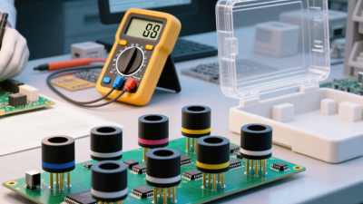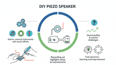
A piezo speaker can sound sharp, thin, or surprisingly clear. Small design choices often decide the result. This guide presents seven practical DIY Piezo Speaker tips for improving tone, volume, and reliability. It focuses on real workshop details, including diaphragm mounting, enclosure space, amplifier matching, wiring, and resonance control.
Professional standards provide useful direction. IEC 60268-3:2018 describes methods for measuring loudspeaker performance, including frequency response and distortion. These measurements matter because a speaker may seem loud while producing uneven sound. The WHO World Report on Hearing, published in 2021, estimates that more than 1.5 billion people live with hearing loss worldwide. It also warns that unsafe listening exposure can create avoidable risks. Better sound should never mean reckless volume.
Industry forecasts also show continuing interest in piezoelectric devices. The MarketsandMarkets Piezoelectric Devices Market report identifies sensors, actuators, and acoustic components as important application areas. However, market figures vary between research firms. That uncertainty deserves attention. A DIY build is not automatically accurate or efficient. A loose ceramic disc can buzz against the housing. Excessive adhesive can dampen vibration. A narrow enclosure can create harsh peaks. Small mistakes become obvious near the ear.
The following tips connect basic acoustic theory with hands-on testing. Try one change at a time. Record the same short passage. Listen from the same distance. A phone microphone can reveal trends, but it cannot replace calibrated equipment. Some experiments will fail. That is part of the process. Good sound often comes from careful adjustment, not expensive parts.
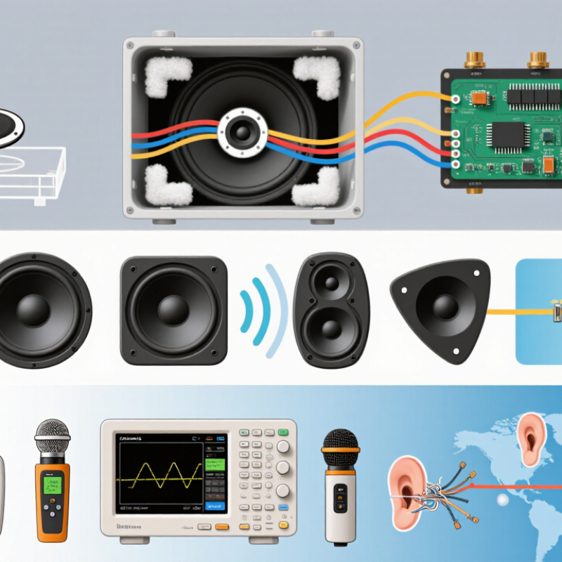
A piezo speaker creates sound when an alternating voltage bends its ceramic element. The bending motion pushes nearby air, but only slightly. That is why piezo units often sound bright, sharp, and weak in bass. On my first DIY prototype, the disc was glued to soft foam. It sounded thin. The mounting absorbed too much movement.
Use a rigid panel for stronger output. Keep the disc flat and secure. Add a small series resistor to reduce harsh peaks and protect the driver from sudden current changes. A simple enclosure can improve acoustic projection, although excessive sealing may create unwanted resonance. Published piezo-transducer studies commonly place useful response near the kilohertz range, not deep bass. Measure it.
Play a slow frequency sweep. Listen for rattling, sudden volume jumps, and narrow resonant peaks. A basic microphone and audio interface can reveal more than guessing. IEC 60268-5 provides methods for measuring loudspeaker frequency response and sensitivity. Use those principles when comparing DIY changes. Human hearing also varies widely. ISO 226 equal-loudness data show that perceived loudness depends strongly on frequency, not pressure alone. Keep the amplifier clean; clipping makes a small piezo painfully brittle. The World Health Organization’s 2021 World Report on Hearing estimates that over 1.5 billion people live with hearing loss, so avoid prolonged high-level testing. I still find enclosure shape difficult to predict. A design that looks efficient may sound worse in the room.

Choosing the Right Piezo Speaker and Audio Components
Piezo speakers are capacitive loads, so the amplifier must tolerate rapid voltage changes. Choose the resonant frequency, sensitivity, impedance curve, and maximum voltage together. A 2024 industry analysis by Grand View Research identifies consumer electronics as a major piezoelectric-device application, but application growth does not guarantee good DIY audio. Check the datasheet. Do not trust appearance.
For speech or alerts, select a unit with a clear response near 2–4 kHz. For musical tones, test beyond that range because many piezo elements sound sharp near resonance. Add a series resistor, often between 22 and 100 ohms, to reduce harsh peaks and protect the amplifier. A small capacitor may form a simple high-pass network, but calculate its cutoff from the speaker’s measured capacitance. Published specifications can vary.
Keep wiring short. Use a stable enclosure. Mounting pressure changes the tone. IEC 60268-5 provides standardized loudspeaker measurement methods, yet small piezo units rarely behave like conventional dynamic drivers. Measure frequency response at one meter when possible. I once blamed the speaker for a brittle sound; the real problem was excessive amplifier gain. That mistake still matters. Start at low volume, compare recordings, and adjust one component at a time. Two identical piezo elements may still sound different because of tolerance, mounting, and enclosure volume.
| Tip | Design Dimension | Recommended Choice | Typical Reference Data | Expected Sound Benefit | Important Note |
|---|---|---|---|---|---|
| 1 | Select the correct operating range | Choose a piezo element whose resonant frequency is suitable for the intended application. | Many small piezo sounders have resonances around 2–5 kHz; audible operation can extend beyond the resonance, depending on construction. | Better output in the target frequency band and fewer harsh peaks. | Resonance frequency is not the same as full-range frequency response. |
| 2 | Match the amplifier to the capacitive load | Use an amplifier that remains stable with capacitive loads and can supply the required AC current. | A piezo element commonly behaves like a capacitor, often approximately 10–100 nF. Current rises with frequency: I ≈ 2πfCV. | Cleaner transients, reduced distortion, and improved reliability. | Check the amplifier data sheet for capacitive-load limits before connecting the element directly. |
| 3 | Add a protective series resistor | Place a small resistor in series between the amplifier output and the piezo element when recommended by the circuit design. | A starting range of 22–100 Ω is often useful for damping switching edges and limiting peak current; final value depends on the amplifier and element. | Less ringing, reduced electromagnetic interference, and lower stress on the output stage. | Too much resistance can reduce maximum output, especially at higher frequencies. |
| 4 | Control excessive low-frequency content | Use a high-pass filter or coupling capacitor if the piezo is not intended to reproduce bass. | A practical starting cutoff for a small piezo tweeter may be 1–3 kHz, adjusted to the measured response and application. | Less wasted amplifier excursion and a clearer, less abrasive midrange. | Use the actual piezo capacitance and connected resistance to calculate the filter accurately. |
| 5 | Use a suitable enclosure or mounting surface | Mount the element firmly on a rigid panel, horn, or small sealed structure according to its intended design. | Rigid mounting generally improves acoustic coupling; panel size, thickness, and damping can shift resonances substantially. | Higher acoustic output and fewer unwanted vibrations from the mounting hardware. | Do not clamp the ceramic disc excessively, as mechanical stress can damage it or alter its response. |
| 6 | Balance brightness with equalization | Apply gentle equalization or attenuation near strong resonant peaks after measuring the assembled speaker. | A 2–6 dB cut can be a useful starting point for a prominent peak, but the exact frequency varies by element and enclosure. | Smoother treble and less listening fatigue. | Avoid boosting frequencies the piezo cannot reproduce efficiently; it may increase voltage without improving sound. |
| 7 | Set safe voltage and test levels | Begin with a low signal level, measure the output, and stay within the piezo element and amplifier ratings. | For a capacitive load, reactive power demand increases with frequency; a 20 V peak signal equals about 14.1 V RMS for a sine wave. | Lower distortion, safer operation, and longer component life. | Do not exceed the specified voltage, temperature, or mechanical excursion limits. |
Measurement reminder: Final component values should be verified with the assembled piezo speaker, because frequency response depends strongly on the element, mounting method, enclosure, amplifier, and listening environment.
A piezo speaker can sound surprisingly clear, but its mounting often matters more than its size. A rigid mounting surface helps transfer vibration evenly. Thin plastic panels may buzz or produce a sharp, unpleasant edge. Use a small rubber gasket between the speaker and panel. It reduces rattling without isolating too much sound.
Avoid excessive screw pressure. I once tightened a ceramic element too firmly, and its output became weaker and harsher. Gentle, even pressure worked better. Leave enough space around the vibrating surface. Wires should have strain relief, because a loose lead can create an irritating mechanical noise. Short listening tests are useful. So are simple frequency sweeps.
The enclosure should control reflections, not merely hide the component. A shallow cavity can improve clarity, while an oversized empty box may add hollow coloration. Add thin damping material to selected internal walls, but do not cover the speaker opening. A narrow front opening can increase perceived volume, although it may emphasize high frequencies. I usually test two or three openings with cardboard prototypes before cutting a final enclosure.
My first design was too rigid and too bright. That mistake showed me that “louder” is not always “better.” Measure the sound at the intended listening distance, then compare it with normal speech or alert tones. Small changes in cavity depth, gasket thickness, and panel stiffness can produce noticeable differences. Leave room for revision. DIY acoustics rarely behave perfectly on the first attempt.
Acoustic wavelength helps determine how large an enclosure opening, internal cavity, or mounting surface should be. The values below are calculated for sound traveling through air at approximately 20°C, using a speed of 343 m/s.
Lower frequencies have longer wavelengths and usually need larger acoustic paths to develop efficiently. Higher frequencies have shorter wavelengths and are more sensitive to grille openings, sharp edges, loose mounting, and small enclosure leaks. Use a rigid mounting surface, seal unintended gaps, avoid covering the piezo diaphragm, and round or smooth the sound outlet where practical.
Adjusting frequency, volume, and signal quality can transform a small piezo speaker. My first prototype sounded painfully sharp because I drove it near the wrong resonant frequency. Test several tones, such as 1.5 kHz, 2.5 kHz, and 4 kHz, then listen for the clearest response. A frequency sweep is more reliable than guessing. Every piezo behaves differently.
Tip 1: Change volume carefully. A higher voltage can increase loudness, but it may also create distortion or damage the element. Use a suitable resistor and check the circuit’s voltage limits. Short bursts are useful for testing. Constant maximum output is not.
Tip 2: Improve signal quality with a clean square or sine wave. Uneven timing can produce clicks and harsh harmonics. Keep connecting wires short, and place a small capacitor near the circuit’s power connection. I sometimes overlook this step, especially during quick bench tests. That mistake can make a good speaker sound faulty.
Tip 3: Control the duty cycle. A balanced waveform often produces a smoother tone than a heavily uneven one. If the sound remains thin, try a small enclosure or a firm mounting surface. Mounting changes the acoustic result dramatically. Measure the output when possible, but trust careful listening too. My ears are useful, not perfect.
Better piezo speaker sound starts with careful testing, not louder voltage. Check the wiring with power disconnected. A loose terminal can create crackling or sudden silence. Use a multimeter to find broken connections, but do not treat a piezo element like a normal low-resistance speaker. Its reading may appear open or unstable. That result can be normal.
Test with a clean, low-level tone. Sweep through several frequencies and listen for harsh peaks, rattling, or weak output. Piezo speakers often sound brighter when mounted on a firm, lightweight panel. A soft surface absorbs vibration. Try a small enclosure, then compare it with an open mounting. Keep the wires short. Long, thin wires may add noise in sensitive circuits. Polarity is usually less critical for one unit, but it matters when multiple speakers work together.
My early tests were inconsistent. The speaker sounded fine on the bench, then became thin after installation. The mounting surface was the problem. I also used too much drive, which produced distortion rather than useful volume. Add a suitable series resistor when the circuit needs current limiting or smoother response. Keep the test voltage within the component’s specifications. Check the signal source, amplifier output, and ground separately. A second speaker or oscilloscope can confirm whether the fault is mechanical or electrical. Humidity, dust, and a cracked ceramic disc can also change performance. Do not ignore small rattles. They often reveal the real issue.