Leave Your Message

Why Choose a Piezo Load Cell for Precision Measurement?

In demanding test environments, tiny force changes can determine whether a product passes or fails. A Piezo Load Cell converts mechanical force into an electrical charge, enabling sensitive measurement during rapid or changing loads. Engineers use these sensors in impact testing, vibration studies, machining, and material research. The response is fast. Data arrives fast. That speed matters when a force event lasts only milliseconds.

A practical choice begins with the measurement task, not the sensor label. Piezo technology performs especially well for dynamic forces, high-frequency events, and limited installation space. Its stiff construction can provide strong overload resistance and stable behavior in harsh test setups. However, it is not a universal solution. Long-term static measurements may require signal conditioning, charge amplification, and careful attention to leakage. Cable quality, mounting torque, grounding, and calibration can change the result. Small details matter.

From hands-on testing, the best results come from matching sensitivity, range, bandwidth, and environmental protection to the application. Traceable calibration and documented procedures help transform a promising reading into defensible evidence. Manufacturers and measurement specialists should explain uncertainty, temperature effects, and connector requirements clearly. That transparency builds trust. Still, every setup has weaknesses. A rushed installation can make an excellent sensor appear unreliable. This guide examines why engineers choose a Piezo Load Cell, where it excels, and when another option may be wiser.
Why Choose a Piezo Load Cell for Precision Measurement?

What Is a Piezoelectric Load Cell?

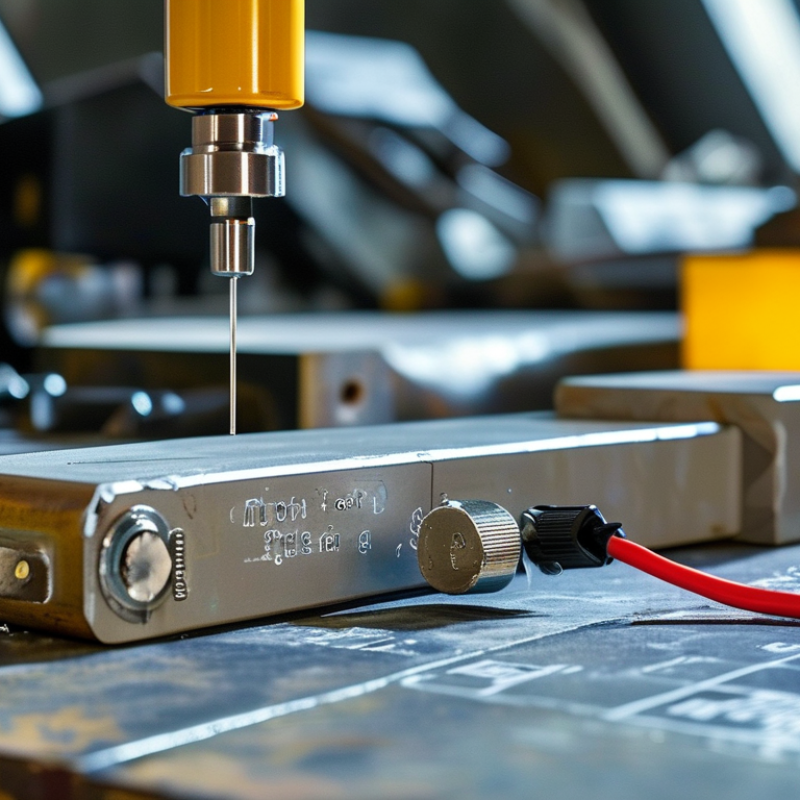
A piezoelectric load cell converts mechanical force into electrical charge. Its crystal or ceramic element deforms slightly under compression, tension, or impact. That deformation creates a measurable charge. A charge amplifier then converts the signal into voltage for recording or control.

It responds quickly. Very quickly.

This makes it useful for presses, fatigue testing, impact measurement, and cutting-force monitoring. Unlike many strain-gauge cells, it is designed mainly for changing forces, not steady loads. A slow force can appear to disappear because charge gradually leaks through the measurement circuit. That limitation is easy to overlook.

The 2024 Piezoelectric Devices Market report from MarketsandMarkets identifies industrial measurement and testing as important application areas. It also forecasts continued market growth through 2029. Such growth reflects demand for high-speed sensing, not automatic accuracy. Installation still matters more than many brochures suggest.

ISO 376:2011 groups force-measuring instruments into accuracy classes from 0.5 to 3. Class 0.5 allows a relative error limit of 0.5% under specified calibration conditions. This figure does not describe every real-world measurement. Cable movement, mounting stiffness, temperature, and amplifier drift can change results.

In bench testing, a rigid load path and correct preload often improve repeatability. Keep the cable still.

A piezoelectric load cell can capture a sharp force peak lasting milliseconds. It may not measure a stable warehouse weight reliably. That mismatch deserves careful review before selecting the sensor.


How Does Piezoelectric Force Measurement Work?

Why Choose a Piezo Load Cell for Precision Measurement?

How Does Piezoelectric Force Measurement Work?

A piezo load cell converts mechanical force into electrical charge. Inside, piezoelectric crystals respond when compressed or sheared. Their atomic structure shifts slightly under pressure. This movement creates a measurable charge across the sensing element. A charge amplifier then converts that signal into a usable voltage. The output follows rapid changes in force with excellent sensitivity. This makes piezoelectric measurement valuable for impact testing, vibration analysis, machining, and material fatigue studies. During testing, I often watch the signal rise within milliseconds. The waveform can reveal contact, rebound, and structural resonance. Small changes matter.

The sensor usually needs a stable preload and a rigid mounting surface. Poor alignment can introduce unwanted bending or side loads. Cable movement may also create electrical noise. Shielded wiring and careful grounding improve measurement reliability. Piezoelectric sensors perform best with changing forces, not steady loads. Their signal can slowly decay under constant pressure. Temperature shifts may affect the crystal and amplifier, so calibration should match real operating conditions. I still recheck mounting torque before critical tests. It seems minor, but it has caused confusing results. A clean installation, suitable signal conditioning, and practical calibration habits help turn a tiny charge into dependable force data.

Why Choose a Piezo Load Cell for Precision Measurement? - How Does Piezoelectric Force Measurement Work?

Measurement Dimension Piezoelectric Load Cell Practical Significance
Operating principle Mechanical force creates a proportional electrical charge in a piezoelectric sensing element. The generated charge is converted into a usable voltage signal by a charge amplifier or an integrated electronics module.
Best measurement type Dynamic force, impact, vibration, oscillation, and rapidly changing loads. It is especially useful when the force changes over milliseconds or when high-frequency detail must be captured.
Static-force capability Limited for long-term static measurement because charge gradually leaks through the sensor and measurement circuit. For stable loads measured over long periods, a strain-gauge load cell is generally more suitable.
Frequency response Typically very wide, with the usable range determined by sensor construction, mounting, cabling, and signal conditioning. A wide response helps preserve transient peaks and dynamic force profiles that may be filtered out by slower measurement systems.
Sensitivity to force changes High sensitivity to rapid changes in applied force and acceleration-related events. This supports accurate analysis of impacts, cutting forces, press operations, engine testing, and structural vibration.
Overload behavior Many designs tolerate short-duration overloads better than their rated capacity, but the specified limit must always be followed. Correct overload protection prevents permanent mechanical damage and maintains calibration stability.
Environmental robustness Generally resistant to high shock and vibration; performance can still be affected by temperature, humidity, cable movement, and electromagnetic interference. Proper sealing, insulated cabling, grounding, and mechanical installation are important for reliable field measurements.
Temperature effects Sensitivity and zero stability vary with temperature and depend on the piezoelectric material and sensor design. Temperature compensation or controlled operating conditions may be required for precision testing.
Signal conditioning Requires a charge amplifier, voltage amplifier, or compatible integrated electronics to convert the high-impedance charge signal. Using suitable signal conditioning reduces noise and prevents errors caused by cable capacitance or insulation resistance.
Mechanical stiffness Typically high stiffness, which helps the sensor respond quickly with limited additional deflection. High stiffness can improve dynamic fidelity and reduce disturbance to the test structure.
Installation requirements Requires a rigid, well-aligned load path and careful control of mounting torque, preload, friction, and unwanted side loads. Good installation practice improves repeatability and helps ensure that the measured force follows the intended load axis.
Typical applications Impact testing, machining, metal forming, vehicle testing, combustion research, vibration testing, and dynamic structural analysis. These applications benefit from fast response, high stiffness, and the ability to capture short-duration force events.
Main advantage Excellent dynamic resolution in a compact and mechanically stiff package. It enables detailed measurement of force peaks, transients, and vibration-related loads.
Main limitation Signal decay and sensitivity to installation and electrical conditions can complicate long-duration or very low-frequency measurements. Application requirements should be reviewed before selecting a piezoelectric design for quasi-static or continuous load monitoring.

Note: Actual performance depends on the sensor construction, rated capacity, mounting method, signal-conditioning equipment, environmental conditions, and calibration procedure.

Key Advantages for Precision Measurement

Piezo load cells offer strong advantages when precision measurement involves changing forces. Their stiff sensing structure responds quickly to impacts, vibration, and repeated compression. This fast response helps engineers capture force peaks that slower sensors may miss. A compact design also fits into limited machine spaces. Less mechanical movement can reduce measurement distortion during rapid testing.

Precision improves when the load path is carefully aligned. Even a small side load can affect readings. In a workshop test, a misaligned fixture may create uneven contact across the sensing surface. Proper mounting, controlled torque, and regular calibration are essential. These details often matter more than the sensor’s advertised resolution. The measurement chain also needs suitable signal conditioning, shielding, and stable cable connections.

Piezo technology is especially useful for short-duration events, such as press monitoring, material impact tests, and tool vibration analysis. It can handle high dynamic loads while maintaining useful sensitivity. However, it is not automatically the best choice for continuous static force. Charge leakage can cause readings to drift over time. That limitation deserves attention. Engineers should define the force duration, temperature range, and expected loading pattern before selecting a sensor. In practice, careful setup usually delivers better results than simply choosing the most sensitive device. Even experienced teams occasionally overlook thermal effects. Rechecking the baseline after a long test can reveal that mistake.

Important Limitations and Selection Criteria

Piezo load cells suit precision measurement when force changes quickly. Their high stiffness captures impact, vibration, and pressing cycles with minimal structural movement. In practical testing, this response can reveal a sharp force peak that a slower sensor may smooth away. However, precision depends on the entire measurement chain. The sensor, cable, charge amplifier, mounting surface, and calibration method all matter.

Important limitations deserve careful attention. Piezoelectric elements generate charge, not a stable long-term static signal. Leakage can distort readings during slow loads or extended holding periods. Temperature also changes sensitivity and creates drift. NIST Technical Note 1297 identifies repeatability, resolution, drift, and environmental effects as key uncertainty contributors. ISO 376 defines force-measuring instrument classes from 00 to 2, but compliance alone does not guarantee suitable dynamic performance. A laboratory should verify behavior under its real loading profile.

Selection should begin with force range, overload protection, operating temperature, frequency response, and installation stiffness. Choose a rated capacity above the normal peak, but avoid excessive oversizing; small signals then consume less of the available resolution. Check the amplifier’s input range and cable compatibility before ordering. A calibration certificate is useful, not magical. It cannot correct poor alignment, uneven contact, or a loose fixture. I have seen clean laboratory data become unreliable after one careless mounting change. That uncomfortable detail deserves more attention.

Common Applications and Installation Practices

Piezo load cells suit measurements where force changes quickly. They capture impacts, vibration, and short pressure events with excellent responsiveness. Engineers often use them in cutting-tool tests, press monitoring, engine development, and material impact studies. They also help detect force changes during automated assembly. Static force measurement is less suitable, because piezoelectric sensors gradually lose charge under constant loads.

Installation affects accuracy more than many teams expect. Mount the sensor on a rigid, flat, and clean surface. Uneven contact can create false readings or uneven stress. Use the recommended preload and tighten fasteners evenly. Keep the signal cable short when possible. Secure it away from motors, switching devices, and moving parts. Proper shielding and grounding reduce electrical interference. Temperature changes can also affect results, so allow the sensor to reach operating conditions before testing. In practice, rushed installation remains a common weakness.

Tips: Check the mounting surface with a straightedge. Record torque values during installation. Calibrate the complete measurement chain, not only the load cell. Watch the first test signal carefully. Unexpected spikes may show loose hardware, cable movement, or poor alignment. Even experienced technicians can overlook cable strain. Review the setup after each major test change.